|
Role
In order to have an effective information system, the end product
must be what the user wants, and must be usable by the requesting
agency. This may be in the form of “just-in-time” or
premeditated requests for mine data, victim data, mapping products
or input to public information reports. Importantly the product
must be accurate, and capable of being produced in a timely manner.
The Information Section manages IMSMA,
and is the hub of MACC SL for mine action information. Full reliance
is placed on this section to provide support to Operations in
all respects; planning, monitoring and recording the details of
the work completed on the various task sites.
IMMSA is where mine-action, victim, and socioeconomic
data in addition to the supporting geographic data is stored,
analyzed, and queried for information of relevance to the demining
operations on the ground.
For details of the staffing of the MACC SL Information Section
see Structure
of the UN component and the LAF/NDO component.
In addition to these staff the MACC SL contracts a network administrator
on a part-time basis.
Implementation
IMSMA is located both in the MACC SL and the
National Demining Office (NDO) in Beirut, and Version 3 has been
in use since July 2003.
Synchronization between the two databases is taking place on a
continual basis, having commenced following the initial implementation
at the NDO in 2001.
To assist in the access of mine action information
by our partners the MACC SL have installed read-only versions
of IMSMA into the Tyr office of the United Nations Development
Programme (UNDP), and the office of BACTEC, the mine clearance
company for the Operation Emirates Solidarity (OES) project. These
are updated on a monthly basis.
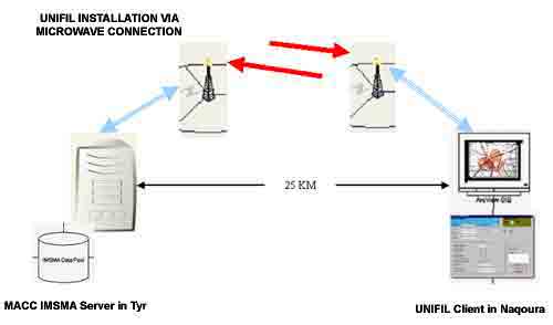
An installation was completed early in
2004 in the office of the Demining Coordination Centre (DCC) at
UNIFIL in Naqoura. This was facilitated by microwave connection
across a distance of approximately 25 kilometres, and enables
the staff at DCC to have a virtual ‘real time’ view
of the database.
|
|
| |
UNIFIL Installation via
Microwave connection
|
|
| |
|
|
| |
|
|
|
| |
Priority
Setting Methodology used for Operation Emirates Solidarity in south
Lebanon
Introduction
Due to the time frame taken from the conception
of OES to actual operations on the ground and the lack of any
Landmine Impact Survey information at the planned start of operations
in May 2002 the MACC SL in consultation with the National Demining
Office (NDO) devised a basic Priority Setting Methodology to allow
the MACC SL Operations Department to organize and plan a works
schedule. Using the methodology described below the MACC SL was
able to identify the most highly affected villages, which allowed
for the priority of effort to be directed at these villages immediately.
The methodology used for Priority Setting was
first used by the UNMACC in Kosovo and has been developed and
applied here in Lebanon with success. This methodology does not
take into account any socio-economic benefits or blockages, but
allows a quick method of categorizing affected areas into high,
medium or low impacted.
The methodology was based on a scoring mechanism
derived from the analysis of the “livelihood space”
of a village. The concept of the “livelihood space”
was first developed by the Vietnam Veterans of America Foundation
in cooperation with the UNMACC in Kosovo, as a means to classify
affected communities in Kosovo by the severity of socio-economic
impacts caused by landmines and unexploded ordnance, following
their conflict.
In countries where a Landmine Impact Survey (LIS) has been conducted
this mechanism could provide the means for determining priorities
for minefield clearance. While a LIS has now been completed for
Lebanon the survey commenced around the same time as the OES project
so results were not available to assist in priority setting.
Aim
The aim of this Priority Setting Methodology
was to assist operational planning by directing clearance assets
first to those villages identified as highly impacted by landmines.
Priority Setting Methodology
The methodology uses a system of buffer zones
around affected areas. Using IMSMA and a GIS, buffer zones of
500 metres and 1000 metres were created around all villages, whilst
along each side of main roads, rivers and other water sources
a 200m buffer zone was created.
Villages with minefields or dangerous areas
within 500 metres of their centre were considered as “highly
impacted” by landmines. The 500m buffer was based on a social
science theory suggesting that children of 5 to 8 years of age
are unlikely to walk further than this distance from their village
centre. Children younger than this would be assumed to be under
the supervision of their parents. While children older than this
can be assumed to venture further than 500 metres from their village,
if they are advised of the danger, they are old enough to understand
the difference between safe and unsafe behaivour.
Villages with minefields and dangerous areas from 500m out to
1000m of their centre were considered to be “medium impacted”
by landmines. Within this additional distance from a village centre
people would be expected to visit periodically to attend to agriculture
fields.
The 200m buffer zone along each side of main
roads and water sources corresponds to the expected movement zones
of the community along and around these features. Minefields and
Dangerous Areas falling within this 200m buffer zone were also
considered to be “highly impacted” areas.
Any Minefields or Dangerous Areas falling outside
any of the above buffer zones were considered to be “low
impacted” areas.
IMSMA Mapping
The following images produced from IMSMA shows
the application of the priority setting methodology buffer zones
on a map using GIS for the area of Al Bayyadah, which is within
Operation Emirates Solidarity Area of Operations No.1. (OES.1.).
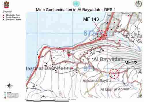
Minefields MF/143 and MF/23 as indicated in
Figure.1. illustrates the basis of the Priority Setting Methodology
explanation at the various stages.
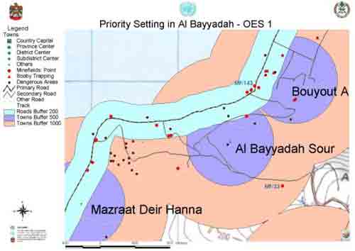
The buffer zones are then applied as shown
in Figure.2.
|
|
| |
|
|
| |
|
|
| |
Figure.1.
Shows the Minefield and Dangerous Areas as point references within
the
Al Bayyadah area, MF143 and MF 23 have been indicated.
|
|
| |
|
|
| |
Figure.2.
The 200m, 500m and 100m buffer zones have been applied
around village centers and roads as applicable
|
|
| |
Minefield number 143 for example
is regarded as a “high threat” minefield since it is
included within both the 500m village buffer and the 200m road buffer
simultaneously. Minefield number 23 on the other hand, is regarded
as being a “medium threat” minefield as it is located
within the 1000m village buffer only.
General Concept of Clearance Operations
Once this Priority Setting Methodology has been applied through
IMSMA and GIS the MACC SL in consultation with any national requirements
will allocate OES clearance assets to those areas highly affected.
This will also be confirmed on the ground by the MACC SL Plans
Officer and any additional local information or concerns raised
through the Community Liaison Team will also be considered.
To allow the most effective use of clearance assets the MACC
SL grouped targets into geographical areas and issued these targets
as a Task Dossier. The Task Dossier, may include one, or up to
as many as ten Minefields or Dangerous Areas. The clearance organisation
would then deploy assets to this area and clear all Minefields
or Dangerous Areas within that geographical area, starting with
the highest down to the lowest priority targets.
This method of operation meant that once an area or village was
completed then the clearance assets could be redeployed to the
next highly impacted village or area. Due to the short time frame
of OES (2 years) and the number of assets on the ground this method
of operations was acceptable to the local community and also the
clearance organisations.
So instead of clearing all high threat targets, throughout the
OES area then returning to clear all medium threat targets and
then returning again to clear all low threat targets the clearance
organisation cleared all targets within that Task Dossier area.
This had the added affect of reducing the confusion within the
local community as well as making operational control of assets
more efficient.
|
|
| |
|
|
| |
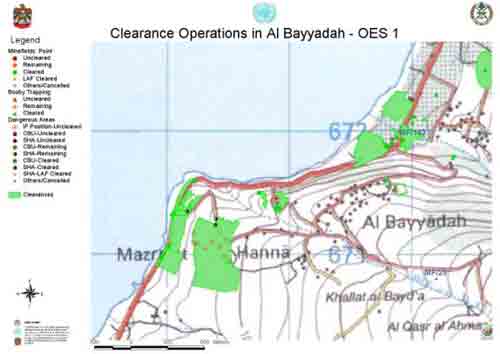
Figure.3.
Shows the final clearance parameters as entered
into IMSMA from the final QA Completion Report
|
|
| |
Note:
- If no hazard is located at the suspected area, the area may
go through a formal “Cancellation” process. The
area is then recorded as a Cancelled Area within IMSMA, such
as the case with MF/23.
|
|
| |
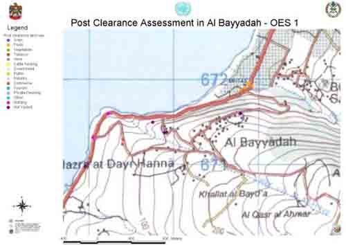
Post Clearance Assessment
of Cleared Areas The
final stage of the clearance process is presented in Figure 4.
This stage focuses on the post clearance use of the formerly mined
area; identified as either private or public and by activity ranging
from various types of agriculture, to industry, to commerce…….
This is based on the application of a Post Clearance Review data
to the cleared areas. The Post Clearance Review of former Minefield
number 143 for example indicates that the land is being used for
agriculture, specifically to grow fruits (banana crops) (See Photo
Gallery “Swing Gate
Charlie” feature for photographs of MF 143 site)
|
|
| |
|
|
| |
Figure.4.
Shows Post Clearance land use
|
|
| |
Outputs
The outputs of
the Information Section through their use of IMSMA are as follows:
- A real time image of the status of mine action
within the project area indicating areas cleared, and remaining
mine contamination analysed as either Minefields, Booby traps,
Dangerous Areas identified through the work of the Community
Liaison or Suspected Hazardous Areas.
- A reflection of land use through the entry
of Pre and Post clearance land use gathered from the Post
Clearance Review.
- Task Dossiers for each area or task
to be either surveyed or cleared by the mine clearance contractors.
The dossier in addition to General Survey data gathered contain
maps relating to the area and the Clearance Plan. See Example
Clearance Plan and Example
Task Dossier.
- Situational maps reflecting the status
of the project at any given time for use by Operations staff
and Community Liaison team members, as well as other stakeholders
working in the area, for eg. UNIFIL.
- Analysed geographic data (shape-files, satellite
imagery, scanned maps)
- A regularly updated and maintained system
of information archive.
- Statistical information on area cleared,
items destroyed, and mine incident and accident victims on a
user request basis for use in monthly, quarterly and annual
reports.
- An integrated spatial information infrastructure
establishing a common ground of coordination between the various
parties (UN, other NGO’s, and the Lebanese Government).
- Trained staff from local organizations on
the use of IMSMA and GIS as part of the UN Policy to coordinate
and collaborate with National Organizations.
IMSMA Version
3
Version 3 has provided opportunities to further
enhance the use of the IMSMA database, as well as increasing its
security features, backup capabilities, reliability and other
general features.
In the MACC SL Version 3 has been used to provide the following
enhancements to Mine Action information and Users alike.
MRE Activity
The addition of the MRE Activity module within IMSMA has now made
it possible to record the Community
Liaison activity conducted within the OES project.
A small adaptation to this module has also made
it possible for the MACC SL to record the conducting of the Post
Clearance Review as a further activity within this module.
This activity is also conducted by the Community Liaison team,
and seeks to confirm confidence in the cleared land some months
following clearance.
Link Databases - For
details of this see Customisations
For more thoughts on Version 3 from Users visit
James
Madison University
|
|
| |
CUSTOMISATIONS
Dangerous Area (DA)/Minefield (MF)-
Type and Status storage and symbology
|
|
| |
DA and MF forms have been customized
for storing and symbolizing various Dangerous Areas based on TYPE
(Booby Trapping, CBU,SHA ,UXO, IF position) and STATUS (Cleared,
Uncleared, Restricted, Cancelled). |
|
| |
|
|
| |
Post Clearance Review-
Land use analysis
|
|
| |
Adding a Post Clearance Review sub-form
for the Minefield and Dangerous Area forms in an attempt to keep
track of the development taking place within the cleared areas.
Minefields formerly represented as red dots can now be represented
by various colors depending on the type of development taking place
in those former hazardous areas.
|
|
| |
|
|
| |
MACC SL Add On Development
MACC SL Information Section has developed two Add-On
databases that contribute to the overall mine action data management
procedures at the MACC SL. These databases cover Plans and Quality
Assurance (QA) Modules. The two databases were developed based
on the needs and requirements of the Plans and QA Sections. A
brief on the functionality of both is provided:
Plans Database
The Plans Database is an IMSMA - linked database that focuses
on grouping the Minefields (MF) and Dangerous Areas (DA) in IMSMA
into corresponding Task Dossiers that are assigned from within
the database, in addition to assigning the operational status
of these Minefields and Dangerous Areas.
Furthermore, this database offers the capability to monitor the
ongoing operational clearance activities on theseMF’s and
DA’s. This is done through the ability to print updated
Status Summary Reports, in addition to up-to-date GIS maps that
through the performance of a graphical/visual analysis compare
the present status with previous ones. This is possible using
the IMSMA GIS mapping capabilities.
Quality Assurance
As for the QA Database, it is a stand-alone database at present
that is linkable to IMSMA. Linkage will be based on future requests
from the QA section. This database is intended for the entry,
analysis, and retrieval of records based on the Quality Assurance
forms that are completed in the field for each individual MF or
DA. Statistical reports based on evaluation, date, and QA inspector
could be produced, in addition to the retrieval of information
relating specific Minefield records to its corresponding QA forms.
|
|
| |
What's
New?
|
|
| |
Combining GIS data and Remote sensing
techniques for detecting agricultural areas and water sources in
relation to hazardous locations/suspected areas
|
|
| |
|
|
| |
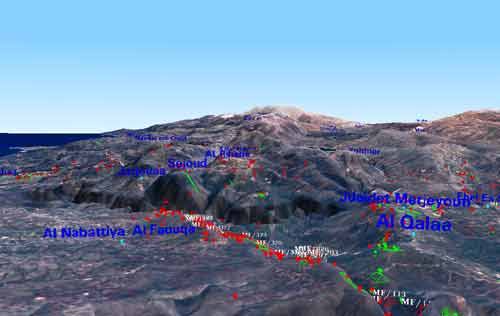
3D visualization techniques
|
|
| |
|
|
| |
|
|
| |
Background
International Management
System for Mine Action (IMSMA)
Development from Versions (V) 1.0 to 3.0
The Swiss Ministry of Defense,
through the Centre for Security Studies and Conflict Research
at The Swiss Federal Institute of Technology Zurich (ETHZ),
sponsored the development of IMSMA as part of Switzerland’s
commitment to humanitarian demining. The software development
team engineered IMSMA as a highly customized Microsoft Access
database so any group using small-office PCs could use the system.
In 1999, the UN Mine Action Service
(UNMAS) declared IMSMA its standard mine information database.
The Geneva International Centre for Humanitarian Demining (GICHD),
founded in 1998, began training and implementation as a partner
with ETHZ.
Using ArcView software, ETHZ developed IMSMA Geographical Information
System (GIS), a custom version of ArcView optimized for mine
action.
GIS allowed presentation and analysis of mine action information
(vector data) on maps and imagery (raster data).
UNMAS began encouraging the use
of IMSMA in its mine action projects throughout the world. IMSMA
V2.0 was developed and distributed during 2000 to 2002, adding
a tasking tool and improved GIS engine.
ETHZ developed IMSMA V3.0 between
2002 and 2003, and it was released by the GICHD in June 2003.
This version offers many improvements including increased capacity,
better back-up facilities, multi-layered security levels, an
ability to link other databases through a user interface, and
the introduction of the Mine Risk Education (MRE) Activity module.
IMSMA Version 3.0 database is a user-friendly database system
that employs a MS SQL Server 2000 as a backend database, MS
Access 2000 as a front-end interface, and ArcView 3.3 as the
GIS Platform.
|
|
| |
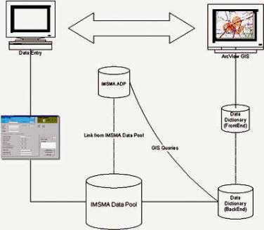 |
| IMSMA V3.0 users only need to work with
the Access front-end and ArcView GIS interface with a high-performance
back-end SQL Server data |
|
|
| |
|
|
| |
|
|
| |
|
|
| |
|
|
| |
Copyright ©2004
MACC SL - All Rights Reserved |
|
|